
Industrial Ozone System Utility Requirements: A Site-Preparation Checklist
Prepare power, feed gas, cooling, ventilation, drainage, layout and control interfaces for an industrial ozone system using a responsibility-based site checklist.
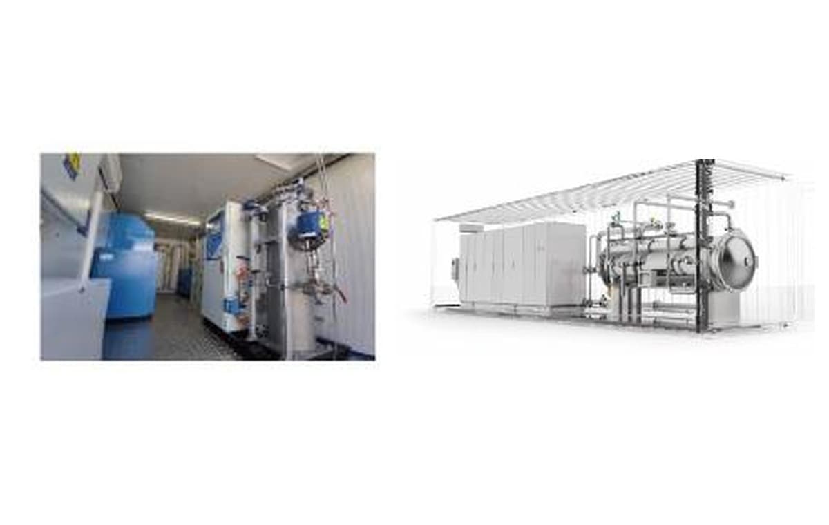
Short answer: there is no reliable model-independent utility table for an industrial ozone system. First define the treatment duty and feed-gas route, then obtain the selected supplier's project utility schedule and general arrangement drawing. Close every power, gas, cooling, room, process and control interface with a named owner, a supporting document and a status of confirmed, pending or not applicable.
An ozone rating in g/h or kg/h does not determine the installation by itself. Two systems with the same nominal output may use different feed gas, ozone concentration, gas flow, cooling architecture, unit arrangement, electrical loads and control interfaces. Ambient conditions and the boundary between supplier, owner and EPC can change the site work again.
This checklist helps plant engineers, EPC teams, integrators and technical buyers prepare the site before installation. It does not publish universal power consumption, cooling-water flow, oxygen quality, ventilation rate, alarm setpoint or service clearance. Those values must come from the selected equipment, the actual location, the project risk assessment and the applicable local requirements.
Why is kg/h output not enough to define site utilities?
Ozone output is one result of the treatment design. Utilities belong to the equipment configuration that produces and applies that output. The dependency normally runs in this order:
- Define the treatment objective, process position, normal and peak flow, water or gas conditions, operating hours and required availability.
- Establish the required ozone duty and what the dose basis means. The industrial ozone-generator sizing guide explains generated, applied and transferred ozone.
- Select the feed-gas route: conditioned air, on-site oxygen generation or supplied oxygen.
- Select the generator family, gas concentration, unit arrangement, turndown and supporting subsystems.
- Issue the model- and project-specific utility requirements, connection points and control interfaces.
- Compare those requirements with the actual site and close every gap before delivery and commissioning.
Utility dependency chain
Site requirements follow the selected system—not kg/h alone
Close the decisions from left to right. A generic utility table skips the project choices that determine the actual connections.
Define treatment duty
Flow, water or gas conditions, objective, operating envelope
Choose feed-gas route
Conditioned air, on-site oxygen or supplied oxygen
Select the package
Output, concentration, unit arrangement and auxiliaries
Issue interface data
Utility schedule, GAD, terminations, I/O and battery limits
Close site actions
Named owner, evidence and status for every connection
If the generator and auxiliary scope are still open, start with the industrial ozone-system product hub and complete-system boundary guide. Site preparation becomes reliable only after the proposed equipment boundary is clear.
Which documents should exist before site preparation is released?
A useful site checklist is connected to controlled engineering documents. At minimum, request and coordinate the following deliverables for the selected package:
- Design basis: treatment duty, operating cases, feed-gas route, site conditions and assumptions used for selection.
- Process and instrumentation diagram: process connections, isolation, instruments, off-gas, drains and agreed battery limits.
- General arrangement drawing (GAD): equipment footprint, connection locations, access zones, loads and lifting or removal paths.
- Project utility schedule: required supply conditions and consumption for each selected item and operating case.
- Electrical load and termination schedule: connected loads, supply points, cable terminations, grounding and interfaces to site distribution.
- I/O list: hardwired and communicated signals, signal direction, owner and termination point.
- Cause-and-effect matrix: alarms, trips, permissives, emergency actions and restart conditions.
- Responsibility matrix: supplier, owner, EPC and third-party scope at every physical and information boundary.
A brochure or model table cannot replace these documents. It may help shortlist a 10–800 g/h compact range, 1–10 kg/h selection range or 10–150 kg/h large-system range, but the released project documents must state the actual values.
How should the master utility and interface matrix be structured?
Create one register shared by the package supplier, owner and EPC. Use one row for each connection or decision, not one vague row for an entire utility. The minimum fields are:
- Interface or tag: the connection, signal or requirement being coordinated.
- Site available: the measured or approved site condition, including units and design case.
- Package required: the selected equipment's requirement under the same defined conditions.
- Battery limit: the physical termination point and what lies on each side.
- Owner: one party accountable for providing or completing the item.
- Evidence: drawing, schedule, calculation, certificate, inspection or test that closes the item.
- Status: confirmed, pending or not applicable, with revision and target date where relevant.
Master interface matrix
One row for every site-to-package boundary
Add site available, named owner and status columns in the working project register.
Electrical
Confirm: Supply, load, grounding, terminations
Load and termination schedule
Feed gas
Confirm: Source, quality, pressure, flow, connection
Utility schedule and P&ID
Cooling
Confirm: Water or heat-rejection boundary
Utility schedule and GAD
Room & safety
Confirm: Environment, ventilation, monitoring
Layout and safety review
Process
Confirm: Injection, contact, off-gas, drainage
P&ID and battery limits
Layout & access
Confirm: Footprint, loads, lifting, service access
General arrangement drawing
Controls & I/O
Confirm: Signals, protocol, interlocks, ownership
I/O list and cause/effect
Site available
Document the actual condition
Package required
Use the selected-vendor value
Owner
Supplier / owner / EPC / third party
Status
Confirmed / pending / N/A
Do not mark an interface confirmed because both sides used the word “standard”. Match units, reference conditions, normal and peak cases, connection size or termination, and document revisions. Unknown information should remain visibly pending rather than being replaced by an assumed typical value.
Electrical power and grounding checklist
The electrical review must cover the complete selected package, not only the ozone generator's discharge power. Feed-gas equipment, cooling, pumps, analyzers, heaters, ventilation, destruction equipment, controls and enclosure services may create separate loads and starting conditions.
Confirm:
- site voltage, phase, frequency, earthing system and permitted supply variation;
- normal running load, connected load, starting or inrush conditions and simultaneous operating case;
- number and location of incoming supplies, local isolators, distribution boundary and cable terminations;
- short-circuit, protective-device, grounding, bonding and surge requirements defined by the project electrical engineer;
- essential, standby or uninterruptible loads and what the system must do when power is lost;
- heat released by electrical equipment into the room or enclosure;
- who supplies field cables, trays, glands, disconnects and final connections; and
- inspection, energization and electrical acceptance responsibilities.
Use the supplier's load and termination schedule after the equipment configuration is selected. Do not extrapolate a total installation load from a catalogue-specific kWh/kg figure; auxiliary loads, operating point and project scope may differ.
Feed-gas supply checklist
The feed-gas route affects ozone concentration, gas flow, preparation equipment, power, maintenance and the site connection. A project may use conditioned air, a PSA oxygen-generation system, a VPSA oxygen system for larger plant demand, or supplied oxygen where the project accepts that arrangement.
For the selected route, record:
- source and responsibility boundary;
- required and available composition or purity, moisture condition, pressure, temperature and flow across operating cases;
- normal, peak, standby, start-up and regeneration conditions where applicable;
- filtration, drying, storage, buffering, compression or pressure-control equipment;
- connection location, piping material, cleanliness requirement, isolation and pressure protection;
- analyzers, low-quality or low-pressure permissives and failure response;
- vent, relief and discharge routing; and
- how gas quality and available capacity will be verified before ozone-system commissioning.
No single oxygen purity, dew point, pressure or flow applies to every ozone generator. Use the selected generator's utility schedule and the oxygen-supply equipment's defined delivery conditions, expressed on compatible reference bases.
Cooling water and heat-rejection checklist
Ozone generation produces heat, but the correct cooling arrangement depends on the generator, oxygen or air equipment, power electronics, ambient conditions and package architecture. A project may connect to plant cooling water, include a separate cooling-water and heat-rejection system, or use another approved configuration.
Confirm:
- which equipment requires cooling and whether circuits are shared or separated;
- required and available supply temperature, return condition, flow and pressure at the stated design case;
- water quality, filtration, materials compatibility and treatment responsibility;
- connection sizes and locations, isolation, vents, drains and freeze protection where relevant;
- heat-rejection equipment, outdoor design conditions and the party responsible for rejected heat;
- low-flow, high-temperature, leak and utility-failure detection and response;
- standby philosophy and the effect of cooling loss on ozone generation; and
- flushing, filling, water-quality verification and commissioning method.
Do not use a universal cooling-water ratio or assume that the generator's listed flow represents the complete plant. Obtain the project utility schedule after all heat-producing equipment inside the supply boundary is known.
Equipment-room, ambient and safety checklist
Room design is a site safety and operability task, not a fixed accessory list. Indoor equipment rooms, outdoor skids and containerized ozone systems create different environmental and responsibility boundaries. An enclosure can integrate equipment and internal services, but it does not remove external foundations, power, process connections, heat rejection, access or local approval work.
Coordinate:
- site elevation, indoor or outdoor location, ambient temperature and humidity range, dust, corrosion, weather and flood exposure;
- area classification or other hazardous-location assessment where the project requires it;
- room or enclosure ventilation basis, air intake and discharge locations, and ventilation failure response;
- ambient ozone detection location, alarm and trip philosophy, calibration and responsibility;
- oxygen-enrichment or oxygen-deficiency assessment where oxygen systems or stored gas are involved;
- emergency stop, access control, warning signs, escape route and emergency procedure interfaces;
- noise, lighting, drainage, fire strategy and safe maintenance conditions; and
- the authority, owner standards and local occupational limits that govern the installation.
Ventilation rates, detector setpoints, alarm levels and safety distances must be established by the project risk assessment, applicable jurisdiction and selected equipment documents. A value copied from another country or installation is not automatically suitable.
Process, off-gas and drainage checklist
The utility boundary must connect to the actual treatment process. Confirm how ozone moves from the generator through the injection or dosing system, into the contact stage and through any residual-gas route.
- process flow, pressure and temperature at minimum, normal and peak conditions;
- injection point, mixer, diffuser, side-stream pump and contact-vessel ownership;
- piping material, connection, isolation, non-return protection and safe depressurization;
- contact-vessel gas containment, vent flow and the route to an ozone off-gas destructor where required;
- destructor inlet conditions, discharge location, monitoring and failure response;
- sample, analyzer, flushing and drain streams and where each may be safely discharged;
- backflow, condensate and liquid-carryover prevention; and
- the process permissives required before ozone can be produced and admitted.
An off-gas destructor is not automatically required for every contacting arrangement and is not automatically included in every quotation. Where ozone-bearing off-gas exists, the project must define containment, treatment or recycle, monitoring and safe discharge.
Layout, access and civil-work checklist
A layout is ready only when installation and long-term maintenance tasks can actually be performed. Review:
- equipment dimensions, operating weight, point loads, foundation and anchoring data;
- transport route from site entry to final position, including doorways, turns and temporary openings;
- lifting points, crane or forklift access and the largest maintenance-removal item;
- connection faces and routing space for power, gas, cooling, process, drains and ventilation;
- service access for dielectric components, valves, instruments, filters, analyzers and rotating equipment;
- separation needed for hot, energized, pressurized or ozone-bearing equipment under the project rules;
- future-unit, standby-unit or expansion space only where it belongs to the approved design basis; and
- who seals penetrations, grouts bases, installs platforms and restores fire or weather boundaries.
Use the approved GAD and maintenance instructions. Do not set service clearance from a generic website figure; the required space depends on the selected equipment, access direction and local safe-work rules.
Controls, communications and I/O checklist
The package control system and plant DCS or SCADA need a defined operating relationship. A network cable alone does not establish who starts, stops or protects the process.
Agree:
- local, remote and maintenance control modes and who has command in each mode;
- start permissives such as process flow, feed-gas condition, cooling availability, ventilation and residual-gas readiness;
- alarms, trips, emergency shutdown actions, isolation behavior and restart requirements;
- hardwired signals, network protocol, addressing, time synchronization and cybersecurity boundary;
- analog ranges, engineering units, fail states, signal direction and terminal ownership;
- setpoint ownership, recipe or production-rate demand, turndown and ramp behavior;
- data logging, trends, event history, remote support and access permissions; and
- loop checks, communications tests, cause-and-effect tests and site acceptance records.
Keep the I/O list and cause-and-effect matrix aligned with the P&ID and actual software revision. A generic I/O count or protocol promise cannot replace this signal-by-signal review.
Who owns each industrial ozone-system interface?
The package supplier normally owns the requirements and internal design within its quoted battery limits. The owner or EPC normally owns the site conditions and plant systems outside those limits. That statement is only a starting point: the signed proposal and responsibility matrix must assign every line item.
Responsibility handoff
Close the interface; do not assume the owner
The quotation and responsibility matrix decide the final split for each project.
GUOLIN / package supplier
- Selected-package utility requirements
- Package GAD, terminations and internal controls
- Defined battery limits and package test records
Owner / EPC
- Site utilities and upstream/downstream plant systems
- Civil, room, access and local approval work
- Plant DCS/SCADA integration and field installation
Joint closure
- Connection points and design conditions
- Alarm, trip and permissive cause/effect
- Revision-controlled evidence and acceptance route
For example, GUOLIN may provide an ozone generator, oxygen equipment, cooling equipment, dosing equipment, off-gas treatment, controls and containerized integration as part of a complete project. It does not follow that every item is included in every offer. Final included, optional, owner, EPC and third-party scopes are proposal-specific.
GUOLIN is China’s only publicly listed ozone-system manufacturer, with complete-system design, manufacturing and integration capabilities. That capability supports coordinated package engineering; it does not replace project-specific site data, local engineering responsibility or the agreed commercial boundary.
Ten questions to answer before releasing the site
- Is the treatment duty and operating envelope approved, including normal, peak, minimum and unavailable-equipment cases?
- Has the feed-gas route been selected, and do site supply conditions match the package requirement?
- Does the electrical schedule cover every selected auxiliary and operating case?
- Is the cooling and heat-rejection boundary confirmed for the actual site design conditions?
- Are room, ambient, ventilation, gas-detection and emergency requirements approved under the applicable jurisdiction?
- Are injection, contact, off-gas, drainage and process permissives shown on an agreed P&ID?
- Does the GAD prove delivery, lifting, connection and maintenance access?
- Do the I/O list and cause-and-effect matrix define every command, permissive, alarm and trip?
- Does every interface have one accountable owner and one closure document?
- Are all pending assumptions visible, dated and assigned before manufacture, shipment or commissioning?
For a project-specific review, send the treatment duty, site location and ambient data, available electrical and cooling utilities, proposed feed-gas route, plant control standard, plot or room drawings and any existing P&ID. GUOLIN can use those inputs to identify the appropriate equipment boundary and prepare a coordinated technical proposal through the project-review enquiry form.
Frequently asked questions
What utilities does an industrial ozone system normally require?
The project commonly needs electrical power, a defined air or oxygen feed-gas route, cooling or heat rejection, room or enclosure services, process and off-gas connections, drainage, and control-system interfaces. The exact values and included equipment depend on the selected system and quotation boundary.
Can ozone generator power requirements be estimated from kg/h alone?
No. The total connected and operating load depends on the generator configuration, feed gas, ozone concentration, operating point and auxiliaries such as oxygen generation, cooling, pumps, analyzers, ventilation and off-gas treatment. Use the selected package's electrical load schedule.
How much cooling water does an industrial ozone generator need?
There is no universal flow per kg of ozone. Required cooling flow and conditions depend on the selected generator, feed-gas and power equipment, cooling architecture, ambient design case and water quality. Confirm them in the project utility schedule.
What oxygen purity, pressure or dew point does an ozone generator require?
Those requirements are generator- and configuration-specific. Match the selected generator's feed-gas schedule with the oxygen source's defined composition, moisture condition, pressure, temperature and flow at compatible reference conditions.
Does an ozone generator room need ventilation and ambient ozone detection?
The project must assess ventilation, ozone detection and emergency response for the actual equipment room or enclosure. Rates, detector locations and alarm or trip values must follow the local jurisdiction, site risk assessment and selected equipment documentation rather than a universal website value.
What documents should an EPC request before installing an ozone system?
Request the approved design basis, P&ID with battery limits, general arrangement drawing, utility schedule, electrical load and termination schedule, I/O list, cause-and-effect matrix and responsibility matrix for the selected package.
Who supplies field utilities and connections for a complete ozone system?
There is no universal split. The supplier defines the package requirements and quoted battery limits, while the owner, EPC or third party may provide site systems and field connections. The proposal and responsibility matrix must assign each item explicitly.
Does a containerized ozone system eliminate site-preparation work?
No. A container can integrate equipment, internal piping, wiring and environmental controls, but the project still needs foundations, transport and lifting access, external power, feed gas, cooling or heat rejection, process connections, drainage, communications and local approvals as applicable.
Related articles
Buying Guide
Industrial Ozone Generator Sizing for Water Treatment: Inputs, Calculations, and Limits
Learn how to calculate industrial ozone-generator capacity from water flow, defined ozone dose and transfer efficiency—without confusing generated, transferred or residual ozone.
Buying Guide
What Is Included in a Complete Industrial Ozone System?
See which equipment, controls, utilities and project interfaces may be included in a complete industrial ozone system—and what every proposal must define.