
Industrial Ozone Generator Sizing for Water Treatment: Inputs, Calculations, and Limits
Learn how to calculate industrial ozone-generator capacity from water flow, defined ozone dose and transfer efficiency—without confusing generated, transferred or residual ozone.
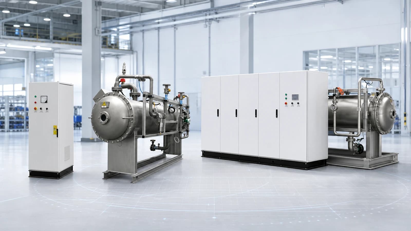
Short answer: size an industrial ozone generator from the actual water-treatment duty, not from water flow or a model number alone. Multiply design water flow by an evidence-based ozone dose, state whether that dose is applied or transferred, and account for gas-to-water transfer only when the chosen dose definition requires it. Then confirm the operating range, feed gas, cooling, safety and complete-system interfaces.
The arithmetic can be straightforward. The design decision behind the arithmetic is not. A generator capacity expressed in g/h or kg/h says how much ozone the equipment produces; it does not say how much reaches the water, reacts with the target, remains dissolved, or satisfies the acceptance criteria. When supplier tables mix g/Nm³, wt%, gas flow and mass rate, use the ozone concentration versus output guide to normalize the generator-side quantities before comparing models.
This guide explains a defensible first-pass calculation for industrial water-treatment projects. It does not prescribe an ozone dose, transfer efficiency, safety margin or regulatory target. Those values depend on the actual application, water chemistry, treatment process and project jurisdiction.
What information comes before an ozone-generator sizing calculation?
Start with the treatment job. A drinking-water oxidation step, municipal wastewater polishing process, industrial effluent project and aquaculture side stream can all involve ozone, but their ozone demand, contacting arrangement, residual risk and acceptance criteria are different.
Before requesting a generator model, define:
- Treatment objective: what must change, where in the treatment train ozone is applied, and how the result will be measured.
- Water flow: minimum, normal and peak flow through the actual ozone-treatment boundary, not simply the total plant nameplate flow.
- Water quality: relevant organic load, suspended matter, target substances, pH, temperature, bromide and seasonal or process variation.
- Dose basis: whether the proposed mg/L value represents ozone generated/applied to the water stream or ozone actually transferred into it.
- Contact and transfer: injection, mixing, diffusion or side-stream configuration; available evidence for transfer under the intended operating conditions.
- Operating envelope: hours per day, peak-duration assumptions, turndown, maintenance arrangements and the required availability philosophy.
- Site interfaces: air or oxygen supply, electrical power, cooling, off-gas management, monitoring and plant controls.
Engineering decision sequence
Size the treatment duty—not just the machine
Five linked decisions prevent water flow, dose and generator output from being confused.
01. Define treated flow
Check minimum, normal and peak water flow at the actual treatment boundary.
02. Verify the dose basis
Document whether the proposed dose is transferred or already applied.
03. Calculate ozone mass
Multiply water flow by the explicitly defined ozone dose.
04. Check the transfer boundary
Correct for project-specific transfer only when the target is a transferred dose.
05. Select the complete system
Confirm generated output, feed gas, turndown, cooling, contact, controls and safety together.
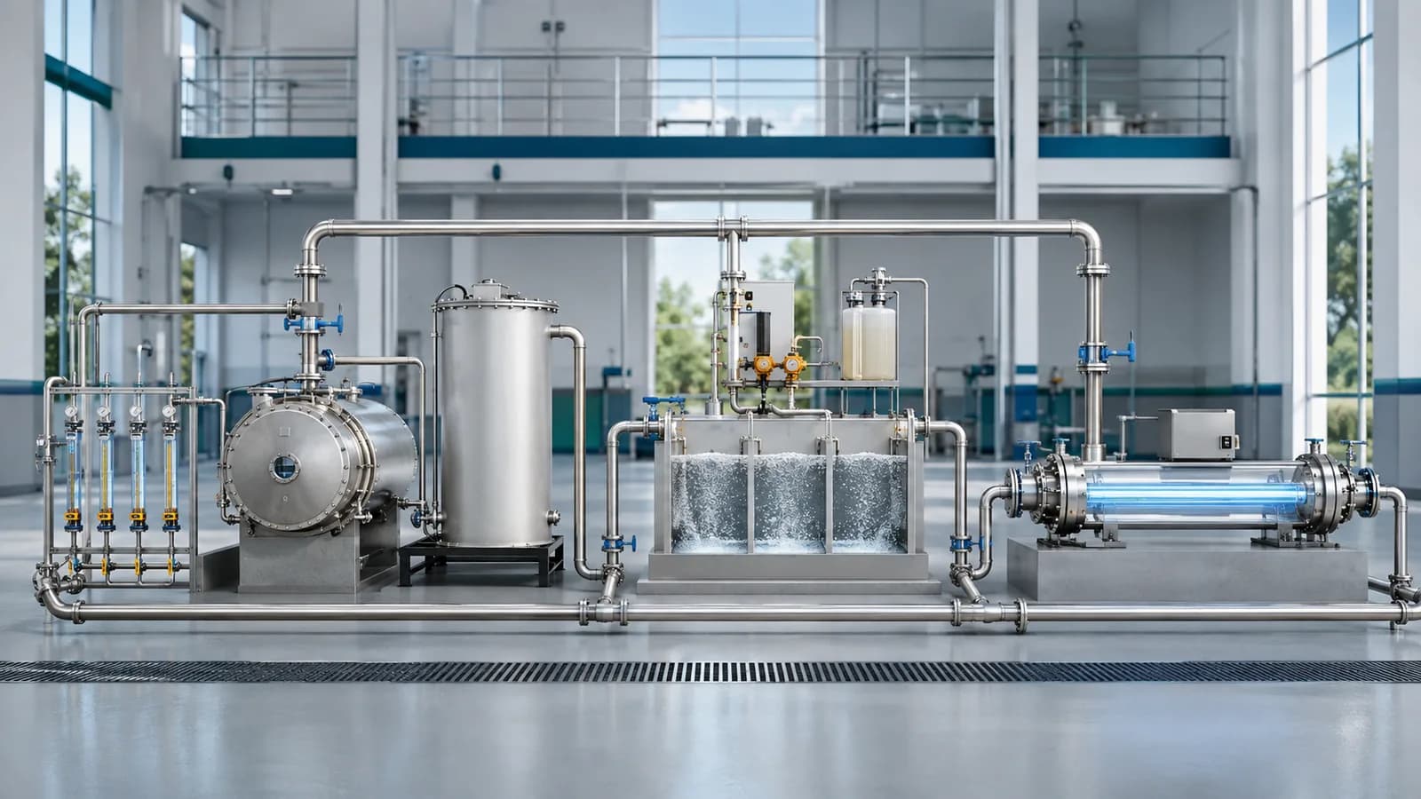
The result is a design basis, not a promise of treatment performance. For the equipment and responsibility boundary around the generator, see what a complete industrial ozone system may include.
What is the difference between generated ozone, applied dose, transferred dose and residual?
These terms describe different points in the process:
- Generated ozone: the mass produced by the generator over time, normally expressed as g/h or kg/h.
- Applied ozone dose: the generated or introduced ozone mass assigned to each unit of treated-water volume, normally expressed as mg/L.
- Transferred ozone dose: the portion that actually passes from the gas phase into the water, also expressed as mg/L but on a different process basis.
- Ozone demand: the ozone consumed by reactions in the specific water and treatment process; it depends on the matrix and objective.
- Dissolved ozone residual: the ozone remaining in the water at a particular sampling location and time after transfer and reactions.
- CT: where relevant to a validated disinfection objective, the relationship between a defined dissolved concentration and an applicable contact time.
Applied dose, transferred dose and dissolved residual may all be reported in mg/L, but that shared unit does not make them interchangeable. A dissolved residual is not the generator output. A gas-phase concentration is not a dissolved-water concentration. And an application-specific CT assessment is not a shortcut for selecting generator mass output.
How do water flow and ozone dose convert to g/h or kg/h?
For water flow expressed in cubic metres per hour and dose expressed in milligrams per litre:
Ozone mass rate, g/h = water flow, m³/h × ozone dose, mg/L.
The unit conversion is exact: one cubic metre contains 1,000 litres, and one gram contains 1,000 milligrams. Those factors cancel, so 1 m³/h × 1 mg/L = 1 g/h. To convert g/h to kg/h, divide by 1,000.
For example, a flow of 120 m³/h multiplied by a defined dose of 2.0 mg/L gives 240 g/h, or 0.24 kg/h, on the same basis as that dose. The crucial next question is whether 2.0 mg/L means transferred ozone or already-applied/generated ozone.
This formula establishes a mass-rate relationship only. It cannot establish whether 2.0 mg/L is suitable for any particular water, contaminant, contactor or treatment objective.
When should transfer efficiency be included in the sizing equation?
Gas-to-water transfer efficiency describes how much introduced ozone crosses the defined gas–liquid process boundary. Its value depends on the contacting arrangement, gas and water flows, mixing, operating conditions and measurement method. It is not a fixed property that can be copied from one project into another.
If the target is a transferred ozone dose
First calculate the ozone mass that must enter the water:
Transferred ozone, g/h = water flow, m³/h × transferred dose, mg/L.
Then calculate the generated requirement using the validated or expressly assumed transfer fraction:
Generated ozone, g/h = transferred ozone, g/h ÷ transfer efficiency as a fraction.
An efficiency of 80% is written as 0.80 in this equation. It is used here only to demonstrate arithmetic; it is not a recommended transfer value or a GUOLIN performance guarantee.
If the target is already an applied or generated dose
When the mg/L value has already been defined as generated ozone applied per treated-water volume, the generator-side mass rate is simply:
Generated ozone, g/h = water flow, m³/h × applied ozone dose, mg/L.
Do not divide by transfer efficiency again. Doing so corrects the same loss twice and inflates the selected generator capacity. If the supplier, consultant and customer use different meanings for “dose,” resolve the definition before comparing equipment offers.
Worked example: the same duty calculated on two different dose bases
Assume a teaching example with 120 m³/h of water and a required transferred dose of 2.0 mg/L. Assume a transfer efficiency of 0.80 solely to demonstrate the calculation. None of these values is a design recommendation.
- Water flow: 120 m³/h.
- Transferred ozone dose: 2.0 mg/L.
- Transferred ozone requirement: 120 × 2.0 = 240 g/h.
- Illustrative transfer fraction: 0.80.
- Generated ozone requirement: 240 ÷ 0.80 = 300 g/h, or 0.30 kg/h.
The equivalent already-applied dose is 2.5 mg/L: 120 × 2.5 = the same 300 g/h. The two routes agree because they describe the same duty at different process boundaries. Applying 0.80 a second time to the already-applied 2.5 mg/L would produce an incorrect larger result.
Illustrative calculation board
One water flow. Two dose definitions. One correct result.
The figures below teach the arithmetic; they are not recommended design values.
Route A: transferred dose
120 m³/h × 2.0 mg/L
= 240 g/h transferred
240 g/h ÷ 0.80
= 300 g/h generated
The 0.80 transfer fraction is an illustrative assumption only.
Route B: applied dose
120 m³/h × 2.5 mg/L
Applied/generated basis
No second transfer correction
= 300 g/h generated
The applied dose already includes the corresponding transfer boundary.
Both routes produce 300 g/h = 0.30 kg/h. Do not apply the transfer factor twice.
If 0.30 kg/h were maintained continuously for 24 hours, the arithmetic daily total would be 7.2 kg/day. That daily figure does not remove the need to verify peak-hour demand, start-up conditions, duty cycle or minimum operating output.
A further caution: estimating transfer from inlet and outlet ozone concentrations alone assumes the gas-flow basis is comparable. Recycle, changing gas volume, leakage, multiple contact stages or unequal inlet/outlet flows require an appropriate project mass balance and measurement plan.
Why can’t the ozone dose be selected from a generic application table?
Two water streams with the same flow can require materially different treatment strategies. Organic matter, target compounds, suspended solids, pH, temperature, upstream treatment and contact conditions all influence how ozone reacts and which outcome can be achieved.
For some wastewater studies, ozone demand is evaluated against dissolved organic carbon or chemical oxygen demand. A value normalized to organic load is not the same thing as a volume-based mg/L dose unless the underlying matrix and conversion are explicitly established. Results from one effluent cannot be automatically transferred to another.
Municipal drinking-water projects also need to assess bromide and potential bromate formation where relevant. By-product risk depends on the actual source water, dose, pH and other treatment conditions; applicable limits are set by the project’s jurisdiction. Increasing ozone output without understanding that relationship can create a control problem instead of solving one.
Municipal wastewater and reuse projects need an appropriate upstream-quality and process-position assessment. Industrial wastewater may vary with production cycles, formulation changes and discharge composition. Aquaculture applications require particular attention to residual exposure, mixing and protection of the cultured stock.
The safe conclusion is not that a particular dose works everywhere. It is that the proposed dose must come from applicable test data, an established design basis or validated comparable operating evidence.
How should normal, peak and minimum operating conditions affect generator selection?
A single nominal capacity can hide an important operating-range problem. Build separate scenarios for:
- Normal duty: the expected routine water flow, matrix and treatment objective.
- Peak duty: the combination of flow, quality and required dose that actually governs the design, including how long that condition persists.
- Minimum duty: the low-flow or low-demand condition that determines whether the generator and contacting system can turn down safely and controllably.
- Maintenance duty: the treatment capacity required while a unit, oxygen train, cooling system or contact stage is unavailable.
- Future duty: a documented expansion case, if the owner has approved one.
Redundancy, duty/standby arrangements, maintenance access and contingency margin are project decisions. A blanket instruction to add a fixed percentage can oversize the equipment, understate a specific failure mode or ignore a more important utility constraint.
Instead, state what each allowance is intended to cover: water-quality variability, seasonal loading, transfer uncertainty, equipment ageing, maintenance availability or expansion. Then agree the value and unit arrangement with the project engineer. No universal safety factor or standby architecture applies to every ozone system.
How do feed gas, ozone concentration and utilities change the selected model?
The required mass output is only one model-selection input. An air-fed and oxygen-fed configuration can achieve different gas concentrations and require different gas-flow, power, cooling and operating interfaces. The same g/h duty does not make two configurations interchangeable.
On the gas side, a consistent calculation is:
Ozone gas mass rate, g/h = gas-phase ozone concentration, g/Nm³ × gas flow, Nm³/h.
This relationship is valid only when concentration and flow use the same defined normal temperature and pressure reference. Weight percent describes a different basis and requires the relevant gas mass-flow and composition information. Gas-phase g/Nm³, gas-phase mg/L, weight percent and dissolved-water mg/L must not be compared as though their denominators were the same.
Final selection should therefore confirm:
- Feed-gas source, supply responsibility, available pressure, gas quality and operating flow; for some configurations this may include a PSA oxygen-generation system.
- Required ozone production and gas concentration across normal, minimum and peak operating conditions.
- Electrical supply, controls, interlocks and the project-specific cooling and heat-rejection interface.
- Injector, diffuser, side-stream or contact arrangement and the ozone dosing and transfer boundary.
- Residual-gas containment, monitoring and an off-gas destruction arrangement where the process and local requirements call for it.
None of these links implies that the corresponding subsystem is included in every quotation. The final industrial ozone-generator system and responsibility split must be defined for the actual project. Compare the full source train—not a capacity threshold—with the air-fed versus oxygen-fed ozone-generator guide, then use the ozone transfer, contact-time and off-gas guide to close the process-side mass balance.
Once a generator configuration and feed-gas route have been proposed, use the industrial ozone-system utility checklist to compare the selected package requirements with site power, cooling, room, process and control conditions.
When is a bench test, pilot study or treatability review necessary?
Further technical work becomes particularly important when the target reaction is unfamiliar, the water matrix changes substantially, bromide or by-product risk is uncertain, comparable operating evidence is weak, or the contactor’s transfer performance has not been established.
Treatability and validation screen
When should the project pause for testing?
Use uncertainty—not a universal dose table—to decide whether more evidence is needed.
Water and treatment target
- Uncertain contaminant or treatment response
- Changing DOC/COD, solids, pH or temperature
- Limited representative water-quality evidence
Transfer and contacting
- Unproven injector, diffuser or side-stream duty
- Unknown gas/liquid flow or mixing boundary
- No defensible transfer measurement
Safety and by-products
- Bromide or possible bromate formation
- Residual exposure or sensitive downstream process
- Unresolved off-gas or monitoring conditions
Operation and acceptance
- Variable peak and minimum operating conditions
- Unclear endpoint or sampling method
- Undefined maintenance, control or availability case
A useful test does more than produce one attractive mg/L number. It should identify the actual treatment endpoint, characterize representative water, document how dose is defined, examine the intended operating envelope and consider residual/by-product behavior. Where necessary, it should also test the contact arrangement, monitoring method and downstream treatment interaction.
The result may confirm the original design, change the treatment sequence, identify a different contact strategy, or show that another process needs to be considered first. Pilot work is a decision tool—not a guarantee, and not an automatic requirement for every project.
Which GUOLIN ozone-generator range matches a calculated duty?
After the treatment and transfer basis is defined, use the provisional generated ozone duty to narrow the equipment family:
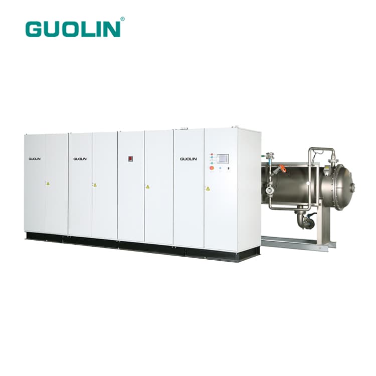
- Compact industrial ozone generators: catalogue models cover 10–800 g/h; duties close to 1 kg/h should be checked against the adjacent selection boundary.
- 1–10 kg/h generator selection range: use this website comparison band for kilogram-per-hour duties after confirming feed gas, concentration, utilities and operating profile.
- 10–150 kg/h large-generator selection range: catalogue-supported air-source configurations within this band extend to 60 kg/h, while oxygen-source configurations extend to 150 kg/h; unit arrangement and project conditions still govern the final proposal.
Across multiple product families and feed-gas configurations, the reviewed GUOLIN catalogue supports a combined 10 g/h–150 kg/h range. It does not describe one model, one standard package or an unconditional output promise. Duties outside a published model table require a project review rather than an assumed standard offer.
What should you send with an ozone-generator sizing enquiry?
A technically useful enquiry should include:
- The application, location and treatment result that must be demonstrated.
- Minimum, normal and peak treated-water flows, including seasonal or production-cycle variation.
- Available water analyses and relevant chemistry, including organic load, bromide, pH, temperature and target compounds when applicable.
- Existing test data, proposed ozone dose and an explicit statement of whether that dose is applied or transferred.
- Known or assumed contact/transfer arrangement and the basis used to estimate transfer.
- Operating hours, duty profile, required availability, maintenance strategy and approved expansion assumptions.
- Available feed gas, electrical power, cooling, installation space and control-system interfaces.
- Any existing process vessels, oxygen plant, injector, monitoring equipment or off-gas treatment that must be incorporated.
- Applicable local process, water-quality and workplace-safety requirements.
- The intended boundary between GUOLIN supply, owner/EPC work and existing plant equipment.
If some inputs are unknown, identify them as unknown rather than substituting a universal dose or efficiency. GUOLIN can review the available data, identify the missing technical decisions and determine the appropriate next engineering step through the project-review enquiry form.
To turn the accepted sizing basis into a comparable supplier request, continue with the industrial ozone-system RFQ specification checklist. It keeps operating cases, scope, guarantees, documents and supplier-stated commercial terms on the same response schedule.
Frequently asked questions
How do you calculate ozone generator capacity from water flow?
Multiply treated-water flow in m³/h by an ozone dose in mg/L to obtain a mass rate in g/h. If the dose is defined as transferred ozone, divide that transferred mass by the project-specific transfer fraction to estimate generated output. If the dose is already defined as generated/applied ozone, do not apply the transfer correction again.
Why does 1 m³/h multiplied by 1 mg/L equal 1 g/h?
One cubic metre contains 1,000 litres and one gram contains 1,000 milligrams. Therefore 1 m³/h × 1 mg/L equals 1,000 mg/h, which is exactly 1 g/h. Divide g/h by 1,000 to express the same mass rate in kg/h.
Should transfer efficiency always be added to the ozone sizing equation?
No. Include a project-specific transfer fraction when converting a required transferred ozone dose into the generated ozone duty. If the specified dose already describes generated or applied ozone per treated-water volume, the transfer effect is already on the other side of the definition and must not be applied twice.
Is dissolved ozone residual the same as ozone dose?
No. Dissolved residual is the ozone remaining in water at a particular location and time after transfer and reactions. Applied dose, transferred dose, generator output and any validated contact-time requirement describe different quantities and cannot be substituted for the residual measurement.
Can one ozone dose be used for every water-treatment application?
No. The appropriate design basis depends on the treatment objective, water chemistry, organic and suspended load, target compounds, pH, temperature, contact arrangement and applicable safety or by-product constraints. Use representative testing or validated comparable operating evidence where necessary.
Should every ozone generator be oversized by a fixed safety percentage?
No universal safety percentage applies. Any allowance should be tied to a defined project risk such as peak water-quality variation, transfer uncertainty, maintenance availability, unit turndown or approved expansion, and then confirmed with the project engineer.
When does an ozone project need pilot or treatability testing?
Testing is particularly useful when the water matrix or target reaction is uncertain, flow and quality vary, transfer evidence is weak, bromate or residual risk must be assessed, or the acceptance endpoint has not been validated. The appropriate test scope depends on the application and available evidence.
Can the same kg/h ozone rating describe different generator configurations?
Yes. The same nominal ozone mass output can be associated with different feed-gas routes, ozone concentrations, gas flows, cooling arrangements, controls and operating envelopes. Confirm the full system and project interfaces rather than selecting equipment from kg/h output alone.
Related articles

Technology
Industrial Wastewater Ozone Treatability Testing: From Bench Test to Pilot Acceptance
Plan industrial-wastewater ozone treatability testing with representative samples, ozone mass balance, dose-response endpoints, pilot scale-up and acceptance gates.
Technology
How to Measure Dissolved Ozone in Water: Methods, Sampling and Control
Compare indigo, membrane, UV, DPD, iodometric and ORP methods; then design sampling, verification and control for dissolved ozone in water.
Application Guide
Ozone in Recirculating Aquaculture Systems: Side-Stream Design, ORP and Residual Control
Plan ozone in RAS: side-stream placement, ORP and residual monitoring, fish and biofilter protection, controls, commissioning and acceptance.
Application Guide
Ozonation for Micropollutant Removal in Municipal Wastewater: Design, Monitoring and Limits
Learn when municipal wastewater ozonation fits micropollutant removal, how to define dose and post-treatment, and what evidence is needed for control and acceptance.
Application Guide
Bromate Formation in Drinking-Water Ozonation: Risk Factors, Control and Monitoring
Understand how bromate forms during drinking-water ozonation, which source-water and process variables change risk, how control options trade off, and what to monitor before design and acceptance.
Application Guide
Ozone-BAC Drinking Water Treatment: Process, Monitoring and Limits
Learn how ozone and biologically activated carbon work together, how BAC differs from GAC, what changes performance, and what to monitor before specifying a drinking-water system.
Technology
Ozone vs Chlorine vs UV for Water Disinfection: How to Choose
Compare ozone, chlorine and UV by treatment role, residual, water quality, by-products, validation and complete-system scope—not by a universal winner table.
Technology
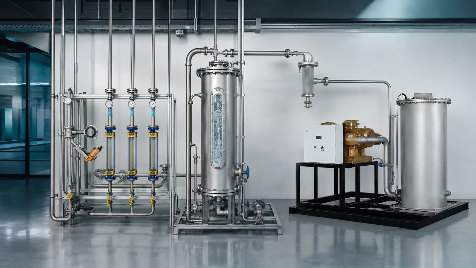
Ozone Mass Transfer, Contact Time and Off-Gas Treatment: An Engineering Guide
Learn how to specify ozone transfer efficiency, contact time, dissolved residual, contactor hydraulics and off-gas treatment as one measurable process boundary.
Technology
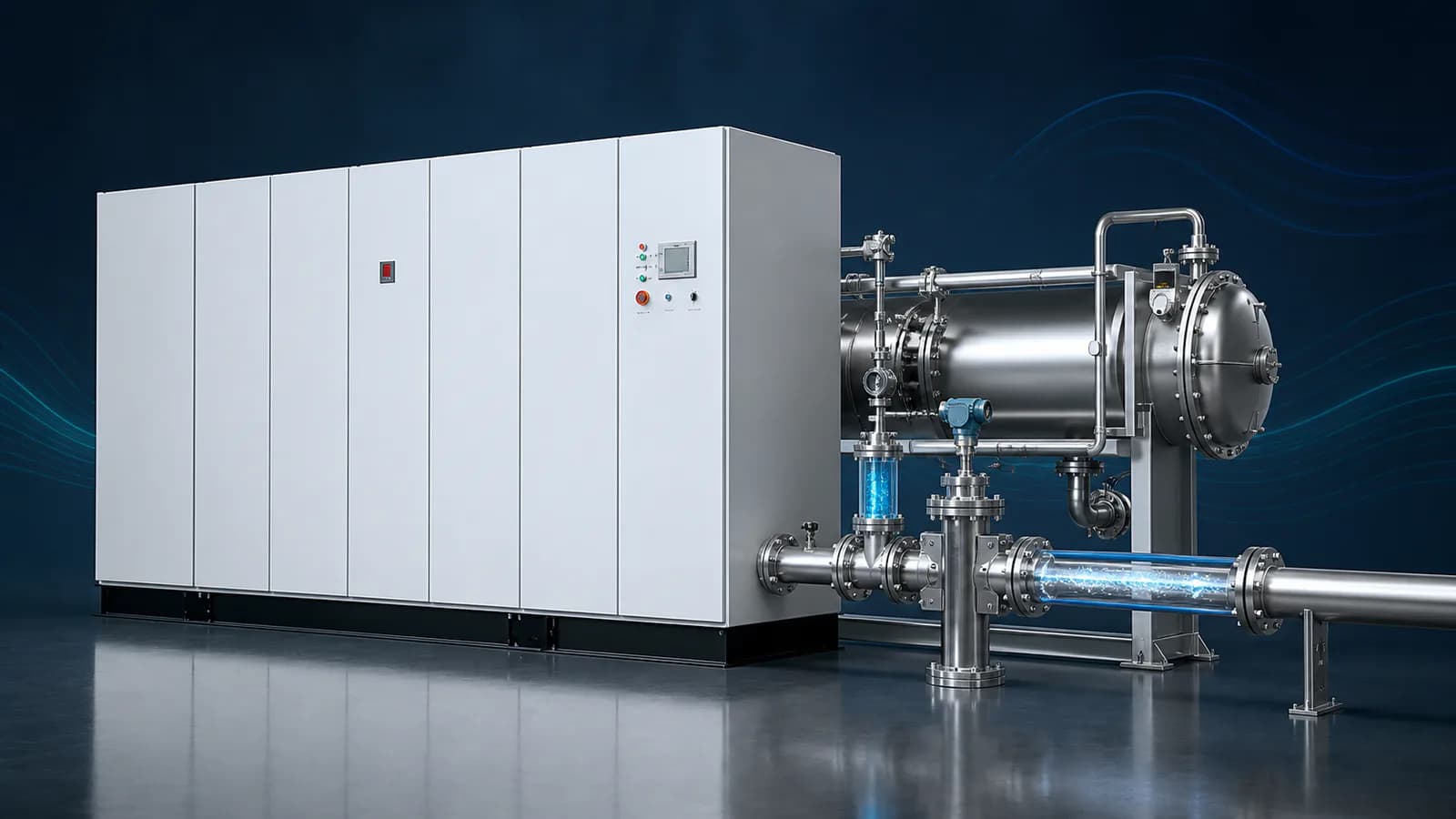
Ozone Concentration vs Ozone Output: g/Nm³, wt%, g/h and kg/h Explained
Learn how ozone concentration, product-gas flow and ozone output relate—and how to compare g/Nm³, wt%, g/h and kg/h without mixing measurement bases.
Buying Guide
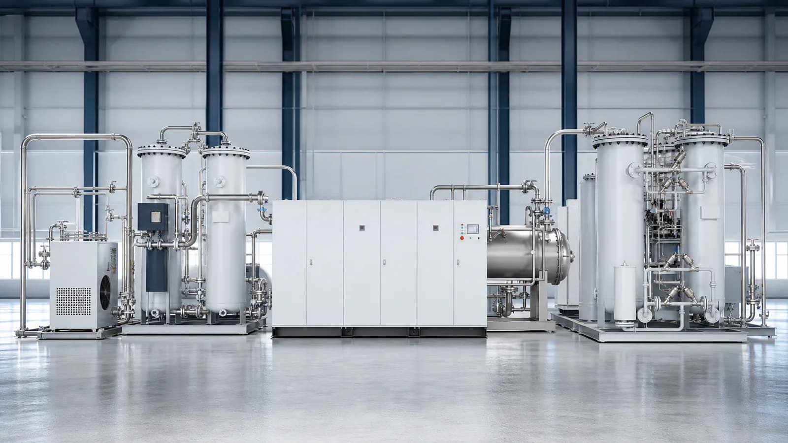
Air-Fed vs Oxygen-Fed Industrial Ozone Generators: How to Choose the Feed-Gas Route
Compare air-fed and oxygen-fed industrial ozone generators by concentration, product-gas flow, utilities, oxygen supply, operating profile and complete-system cost.
Buying Guide
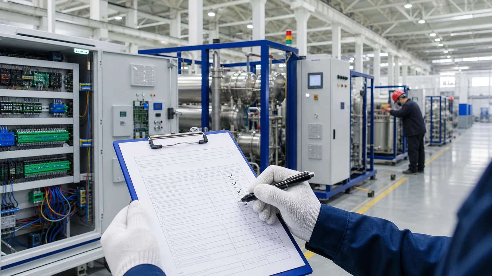
How to Prepare an Industrial Ozone System RFQ: A Specification Checklist
Build a comparable industrial ozone system RFQ with a clear design basis, scope boundary, operating cases, bidder response schedule and acceptance requirements.
Buying Guide
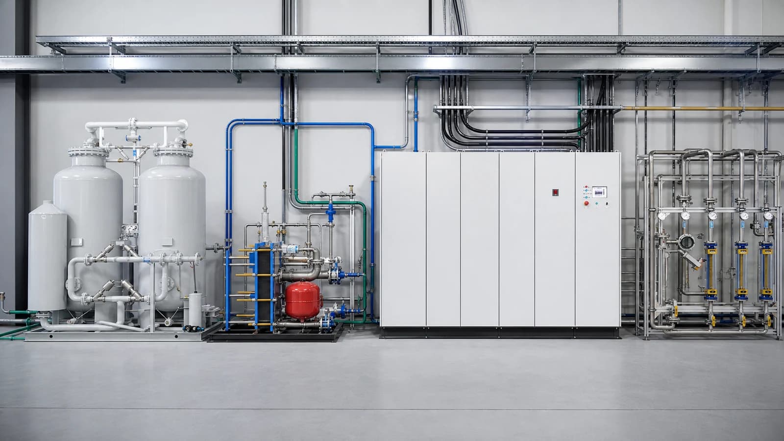
Industrial Ozone System Utility Requirements: A Site-Preparation Checklist
Prepare power, feed gas, cooling, ventilation, drainage, layout and control interfaces for an industrial ozone system using a responsibility-based site checklist.
Buying Guide
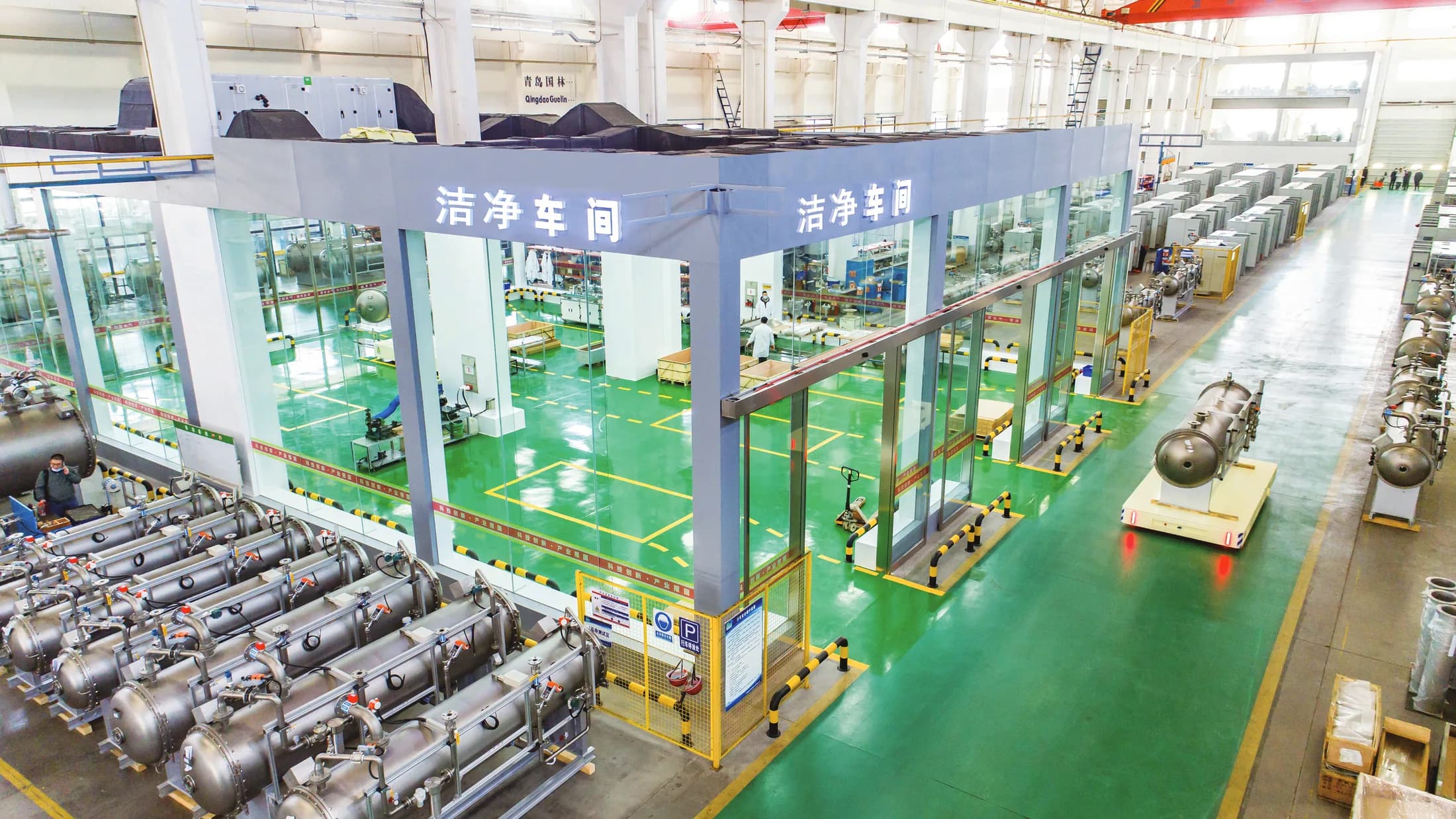
What Is Included in a Complete Industrial Ozone System?
See which equipment, controls, utilities and project interfaces may be included in a complete industrial ozone system—and what every proposal must define.