
Ozone Mass Transfer, Contact Time and Off-Gas Treatment: An Engineering Guide
Learn how to specify ozone transfer efficiency, contact time, dissolved residual, contactor hydraulics and off-gas treatment as one measurable process boundary.
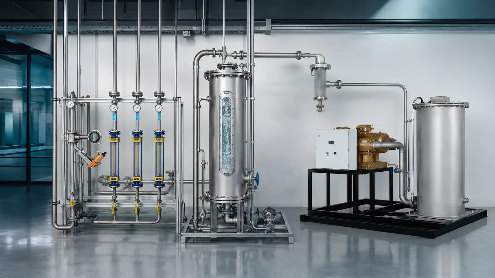
Short answer: an ozone contact system is not defined by one transfer percentage or one contact time. It is defined by a measurable boundary: ozone mass entering the contactor, ozone mass leaving in off-gas, the dissolved-ozone profile in representative bulk water, the hydraulic exposure across minimum, normal and peak operation, and the controlled route from wet off-gas to treatment and monitored discharge. Transfer efficiency, kLa, contact time, CT and dissolved residual describe different parts of that boundary.
This guide is for plant owners, EPC teams, consultants, water-treatment engineers and technical buyers who have moved beyond generator nameplate output and now need to specify how ozone actually reaches the process. It explains the mass balance, contactor choices, measurement points and off-gas data that make two proposals technically comparable.
If the required ozone duty is still unknown, begin with the industrial ozone-generator sizing guide. If g/Nm³, wt%, gas flow, g/h and kg/h have not yet been normalized, first use the ozone concentration and output guide. This article starts at the generator-to-process interface.
Map the ozone mass before choosing a contactor
A complete specification gives each ozone quantity a name, a boundary and a measurement method. Without that discipline, “dose,” “transfer” and “residual” can refer to different numbers in different proposals.
- Generated ozone: ozone mass leaving the generation stage at a declared operating point.
- Applied ozone: ozone mass delivered to the defined contact-system inlet after any stated upstream loss, split or recycle.
- Transferred ozone: the portion of applied ozone that crosses from the gas phase into the liquid within the stated contact boundary.
- Consumed ozone: transferred ozone that reacts with immediate water demand, target compounds or other matrix constituents during the stated period.
- Dissolved residual: ozone remaining in the liquid at a named sampling point and time, measured by a method suitable for that water.
- Off-gas ozone: ozone remaining in gas that leaves the contactor before recycle or destruction.
These quantities can be related by mass balance, but they are not synonyms. Transferred ozone can react so quickly that little dissolved residual remains. A measurable residual can persist even when the target reaction has already slowed. Off-gas can remain a controlled hazard even when the percentage transferred is high.
Ozone mass boundary
Follow the mass—not one percentage
Each quantity needs its own location, time basis and measurement method before the contact system can be reconciled.
Generated
Generator outlet at a declared operating point
Applied
Mass entering the defined contact boundary
Transferred
Mass crossing from gas into liquid
Consumed
Mass reacting with water demand or targets
Residual
Dissolved ozone at a named sample point
Liquid-side balance
Transferred ozone separates into reaction, decomposition and dissolved residual.
Gas-side balance
Untransferred ozone leaves as a wet off-gas stream that still needs a controlled route.
How should ozone transfer efficiency be calculated?
For a defined contactor boundary and steady reporting interval, use ozone mass rate rather than concentration alone:
Transfer efficiency (%) = 100 × (inlet ozone mass rate − outlet off-gas ozone mass rate) ÷ inlet ozone mass rate
Each mass rate requires a representative ozone concentration and gas flow for the same stream, time basis and temperature/pressure reference. Some verification documents show a shorter concentration-only equation, but that form assumes the inlet and outlet gas flows are equal. If gas dissolves, water vapour enters, gas is recycled, leaks occur or the flow basis changes, that assumption needs proof rather than a spreadsheet shortcut.
A fictional mass-balance example
Assume a contactor receives 5.0 kg/h of applied ozone. Its measured off-gas is 25 Nm³/h at 20 g/Nm³, with both values describing the same off-gas stream and reference conditions:
Off-gas ozone = 25 Nm³/h × 20 g/Nm³ = 500 g/h = 0.50 kg/h
Transfer efficiency = 100 × (5.0 − 0.50) ÷ 5.0 = 90%
This arithmetic is illustrative only. It is not a GUOLIN rating, a recommended target or evidence that 4.5 kg/h reached the intended contaminant. The calculation says that 4.5 kg/h crossed the selected gas-to-liquid boundary under the stated test conditions. A process balance still has to separate immediate demand, target reaction, decomposition and remaining liquid residual.
The US EPA equipment-verification protocol is useful because it explicitly separates feed-gas concentration, off-gas concentration, applied dose, transfer efficiency, transferred dose and dissolved residual. Its drinking-water test context does not make its test values universal, but its quantity discipline is broadly useful.
Transfer efficiency, kLa, residual and treatment performance are different
Transfer efficiency is a boundary result
Transfer efficiency is the fraction of incoming ozone mass that does not leave in the measured off-gas over a stated period. It changes when contactor configuration, water flow, gas flow, pressure, ozone concentration, gas-to-liquid ratio, temperature, mixing or water chemistry changes. A value at normal duty cannot automatically be reused at minimum or peak duty.
kLa is a rate parameter
The volumetric liquid-side mass-transfer coefficient, commonly written kLa, combines a liquid-film transfer coefficient with gas-liquid interfacial area per liquid volume. A simplified driving-force expression is often written as rate ≈ kLa(C* − C), where C* is the equilibrium liquid concentration associated with the local gas conditions and C is bulk dissolved concentration.
That relationship explains why bubble size, mixing, pressure, ozone partial pressure, temperature, water chemistry and reactor geometry matter. It does not provide one plant design coefficient. Published kLa values belong to the tested contactor, fluid, scale and method; a laboratory coefficient should not be copied into an industrial guarantee.
Dissolved residual is a local remaining concentration
A dissolved-ozone reading answers what remains at the sampling point, not how much total ozone transferred or which reaction consumed it. The sample line, time delay, pressure release, temperature and analytical method can change the result because ozone reacts and decays. The Standard Methods 4500-O3 B summary describes indigo colorimetry and its interferences; ASTM D7677 covers continuous measurement in a defined low-conductivity-water scope. Neither method should be assumed suitable for every industrial matrix without review.
Treatment performance is the project outcome
Treatment performance depends on the target, water matrix, upstream treatment, ozone exposure, reaction pathway, by-products and the acceptance method. High transfer efficiency does not prove disinfection, oxidation selectivity, colour removal, COD reduction or regulatory compliance. Those outcomes remain with the relevant application solution and validation plan.
What does ozone contact time actually mean?
“Contact time” can refer to at least three different ideas, and a useful specification says which one is intended:
- Theoretical hydraulic detention: vessel liquid volume divided by water flow, commonly written V/Q.
- Effective hydraulic exposure: the residence-time distribution after short-circuiting, dead zones, recirculation and baffling are considered, often investigated with a tracer.
- Chemical or disinfection exposure: the dissolved-ozone concentration profile integrated over the relevant effective time and process zone.
Theoretical detention is a useful first geometry check, but it is not automatically the effective time experienced by the least-contacted water. Two basins with equal volume and flow can have different tracer responses because their inlet, outlet, baffles, mixing energy and recirculation differ.
CT is not just a tank-volume calculation
In a defined disinfection framework, CT represents dissolved disinfectant concentration multiplied by contact time, or more accurately the concentration profile integrated across exposure. The applicable organism, temperature, pH, residual sampling points, tracer method, permitted calculation procedure and authority requirements belong beside the value.
The US EPA microbiological equipment-verification protocol, for example, locates samples in representative main-contactor flow and uses tracer-derived hydraulic factors to account for short-circuiting. That is evidence that method and sampling position matter; it is not a global CT requirement. Oxidation projects that are not claiming disinfection credit may use a different kinetic, exposure or performance-validation framework.
There is therefore no responsible universal answer to “How many minutes does ozone need?” The answer begins with the treatment objective and ends with measured hydraulics, residual or reaction evidence, operating range and the applicable acceptance procedure.
Bubble diffuser or Venturi injector: which contactor should you choose?
Both can be valid. A diffuser introduces ozone-bearing gas through porous elements into a basin or column. A Venturi or injector system uses a pressure differential in a sidestream, commonly followed by in-line mixing, remixing with the main flow and sometimes a degassing vessel. Multistage systems can combine dose points, contact zones or technologies.
Conditional contactor choice
Choose the route that closes the project constraints
No route wins from transfer efficiency alone. Compare hydraulics, pressure, maintenance, degassing, measurement and control range together.
Diffused-bubble basin
Useful when: A suitable basin or column provides depth, distribution and sampling access.
Verify: Gas distribution, baffles, headspace collection and effective hydraulics.
Watch: Fouling, coalescence, shallow zones, dead zones and uneven coverage.
Sidestream injector
Useful when: A pressurized sidestream can be pumped, mixed and returned to the main flow.
Verify: Pressure differential, sidestream range, remixing, degassing and main-flow samples.
Watch: Pump head, pressure loss, turndown and mist or gas release downstream.
Multistage or hybrid
Useful when: Separate dose zones have defined reaction, residual or operating jobs.
Verify: Each stage's mass, exposure, controls, samples and off-gas boundary.
Watch: Added valves, instruments, control logic and unclear package ownership.
Diffused-bubble basin or column
This route can fit a new or existing basin with sufficient liquid depth and a hydraulic arrangement that can be baffled and sampled. Design work includes diffuser material and pore distribution, gas distribution, coverage, basin depth, co-current or counter-current flow, headspace collection, access and fouling/maintenance. A deep tank alone does not prove good gas distribution or effective contact.
Sidestream injector and mixer
This route can fit a pressurized pipe or retrofit where a pumped sidestream, injector and static or purpose-built mixer can be integrated. Design work includes available pressure differential, pump head, sidestream fraction, gas-to-liquid ratio, injector operating envelope, remixing with the full flow, degassing, pressure loss, turndown and representative residual sampling. High local dissolved ozone in the sidestream is not automatically the main-flow residual.
Multistage or hybrid contact
Staging can separate immediate ozone demand from a later residual or reaction objective, distribute gas across variable flows, or combine an injector with a downstream basin. It also adds valves, control logic, measurement points and responsibility boundaries. Staging is useful only when each dose point and contact zone has a defined job and the resulting exposure/off-gas balance can be verified.
GUOLIN's documented project options include ceramic or titanium porous diffusers, Venturi injection, demisting and thermal-catalytic ozone destruction. The ozone dosing and distribution system page owns those equipment routes. Final selection still depends on the project boundary; these elements are not automatically included in every quotation.
What changes ozone mass transfer in real operation?
A contactor should be checked at minimum, normal and peak water flow and ozone duty. The following variables interact; optimizing one in isolation can move a limitation elsewhere.
- Gas-side conditions: ozone concentration and partial pressure, product-gas flow, carrier gas, pressure, temperature, moisture and distribution among contact points.
- Liquid-side conditions: water temperature, pH, ionic strength, dissolved and suspended constituents, immediate ozone demand, surfactants, solids and foaming tendency.
- Interfacial conditions: bubble-size distribution, coalescence, interfacial area, mixing energy and the concentration driving force.
- Hydraulics: water flow, gas-to-liquid ratio, vessel depth, inlet/outlet geometry, baffles, recirculation, short-circuiting and pressure loss.
- Equipment condition: diffuser fouling, injector pressure, pump performance, nozzle condition, gas leaks and instrument drift.
- Control range: how gas, water and ozone settings change together during turndown, peak duty, standby and train changeover.
For example, smaller bubbles may increase interfacial area, but the result can still be limited by coalescence, poor distribution, shallow depth or a high gas rate. More mixing may improve dispersion but add pump energy and pressure loss. Faster liquid-phase reaction can maintain a concentration driving force while leaving little measurable residual. These are reasons to pilot or verify uncertain high-consequence designs, not reasons to apply one generic correction factor.
Off-gas treatment begins at the contactor roof
Off-gas is a process stream, not simply “air from the tank.” The boundary normally begins with a covered or sealed contact zone and continues through gas collection, condensate and entrained-droplet control, optional recycle where technically justified, an ozone destructor, discharge monitoring and the safe release point.
Define the wet-gas envelope
The off-gas schedule should state minimum, normal and peak volumetric flow; inlet ozone concentration and mass rate; temperature; pressure; humidity and condensation risk; entrained water or foam; expected contaminants; operating duration; turndown; and upset cases. A demister, condensate drain, heater or other conditioning step may be needed to keep water from the catalyst or thermal section. Drain and backflow responsibilities must be explicit.
Select the destructor from conditions, not generator nameplate alone
Thermal, catalytic and thermal-catalytic arrangements appear in industrial practice. Equipment selection must match the actual gas envelope, permissible pressure drop, heating/start-up requirement, catalyst condition, redundancy philosophy, outlet requirement, material compatibility, service access and monitoring plan. A percentage or outlet value published for one model at rated flow is not a universal guarantee.
The GUOLIN ozone-destructor page defines the supporting equipment owner. The final proposal must state the inlet design cases, pretreatment/conditioning, supplied controls, outlet acceptance method and the plant/EPC interfaces around it.
Post-destructor and ambient monitoring serve different purposes
A process analyzer before or after a destructor checks a gas stream. An ambient monitor checks the space where people may be exposed. Their ranges, sample systems, alarm logic and calibration needs differ. Applicable exposure limits and discharge requirements come from the project jurisdiction and plant risk assessment; they should not be copied from an unrelated country or old manual.
Official occupational-health sources such as NIOSH confirm that ozone exposure can harm workers, while Safe Work Australia illustrates that legal limits sit inside a wider duty to eliminate or minimize risk. The project cause-and-effect matrix should define alarms, isolation, ventilation response and ozone-generator shutdown with the responsible safety authority.
Build one measurement plan across gas, water and safety
A defensible acceptance test uses instruments selected for the phase and range at each location. At minimum, reconcile these five points:
- Applied gas: ozone concentration and gas flow at the contact-system inlet, time-aligned on one reference basis.
- Contactor hydraulics: water flow, active volume, stage configuration and tracer or other accepted evidence for effective exposure where required.
- Bulk dissolved ozone: representative main-flow sample locations, residual method, sample handling, time delay and calibration/verification.
- Off-gas: concentration and flow before recycle/destruction, plus temperature, pressure, moisture and condensate conditions.
- Controlled discharge and workspace: post-destructor process measurement and separate ambient safety monitoring with approved alarm actions.
Acceptance measurement chain
Five synchronized points make the boundary testable
The instrument, range, sample condition and time stamp matter as much as the reported value.
Applied gas
O₃ concentration + gas flow on one basis
Hydraulics
Water flow, active volume, stage and tracer evidence
Bulk liquid
Representative dissolved-O₃ sample and method
Wet off-gas
O₃ + flow + temperature + pressure + moisture
Controlled release
Post-destructor process check + separate ambient monitor
Declare
Location, phase, range, method and owner
Synchronize
Use the same operating period and aligned time stamps
Accept
State tolerances, duration, records and accountable parties
Record instrument identity, principle, range, sample location, conditioning, calibration/traceability, averaging period, tolerance and data owner. Align all time stamps. A transfer calculation assembled from a peak inlet reading and a later off-gas reading is not a valid simultaneous mass balance.
Copyable ozone contact-system specification block
Use this field set in an enquiry or RFQ. Unknown values can remain TBD, but the responsible party and closure method should be named.
Process water: [minimum / normal / peak flow, temperature, pressure, pH and relevant matrix data]
Treatment objective: [target, upstream/downstream process, performance/validation method]
Applied ozone: [minimum / normal / peak mass rate; gas concentration and flow; reference conditions]
Contact boundary: [inlet and outlet battery limits; new/existing vessel or pipeline]
Contactor route: [diffuser / sidestream injector and mixer / multistage or supplier proposal]
Hydraulics: [active volume, depth/head, pressure loss, sidestream range, baffles, tracer requirement]
Dissolved measurement: [sample points, method, range, sample handling, required residual/exposure if applicable]
Off-gas envelope: [flow, ozone concentration/mass, temperature, pressure, humidity, droplets/foam, contaminants, upset case]
Off-gas scope: [collection, demister, drains, recycle, destructor, fan/blower, discharge point]
Safety and controls: [ambient/process monitors, applicable limits, cause/effect, shutdown, ventilation interface]
Operating cases: [minimum / normal / peak, seasonal, standby, train changeover and redundancy]
Acceptance: [test duration, instruments, calibration, averaging, tolerances, records and accountable parties]
Responsibility: [GUOLIN / customer / EPC scope and every utility/process interface]
Use the site utility checklist to close power, water, pressure, drainage, ventilation and I/O. Use the ozone-system RFQ guide to place these fields inside a comparable bidder-response schedule. If the complete functional boundary is still unclear, return to what is included in a complete industrial ozone system.
The practical buying rule
Do not purchase an ozone contact system from one percentage and one number of minutes. Ask the supplier to close the mass balance, hydraulic exposure, dissolved-residual profile, off-gas envelope and control response at the same minimum, normal and peak operating cases.
That request makes the design reviewable. It shows where ozone is measured, what “transferred” means, whether contact time is theoretical or verified, how wet off-gas reaches the destructor, and which acceptance record proves each boundary. It also prevents a good generator from being paired with an unmeasurable contact process.
GUOLIN is China’s only publicly listed ozone-system manufacturer, with complete-system design, manufacturing and integration capabilities. Send the process flows, water matrix, applied ozone cases, hydraulic constraints, measurement requirements and off-gas envelope through the technical project-review form. GUOLIN can then define a project-specific generator, dosing/contact arrangement, off-gas path, controls and acceptance boundary. The industrial ozone-system product hub provides the equipment-family starting point.
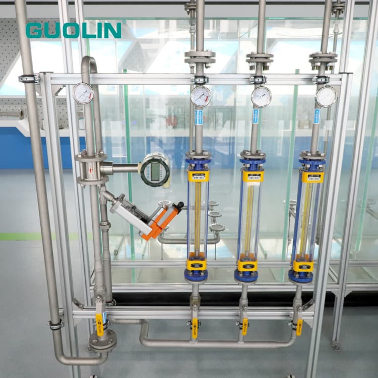
Frequently asked questions
What is ozone mass transfer?
Ozone mass transfer is the movement of ozone from the ozone-containing gas into the liquid across a defined contact boundary. It depends on gas and liquid conditions, interfacial area, mixing, pressure, temperature, contactor geometry, water chemistry and operating point.
How is ozone transfer efficiency calculated?
Use a flow-aware ozone mass balance: subtract the outlet off-gas ozone mass rate from the contactor-inlet ozone mass rate, divide by the inlet mass rate and multiply by 100. Concentration alone is sufficient only when equal gas flows and a common basis are established.
Is ozone transfer efficiency the same as kLa?
No. Transfer efficiency is the fraction of inlet ozone mass transferred across a stated boundary during a test period. kLa is a condition-specific volumetric mass-transfer rate coefficient. Neither should be copied between different contactors or operating conditions without evidence.
How much ozone contact time is required?
There is no universal contact time. It depends on the treatment objective, water matrix, dissolved-ozone profile, contactor hydraulics, operating range, applicable validation method and local requirements. Theoretical vessel volume divided by flow is not automatically effective exposure time.
Is CT the same as hydraulic retention time?
No. Hydraulic retention is a time quantity, while CT is a concentration-by-time exposure defined within a particular validation framework. Residual sampling, tracer-derived hydraulics, temperature, pH, target and the accepted calculation method can all matter.
Is a bubble diffuser or Venturi injector better for ozone transfer?
Neither is universally better. Diffusers can suit suitable basins or columns; sidestream injectors can suit pressurized piping and retrofits. Compare available depth or pressure, water and gas range, mixing, footprint, fouling, maintenance, degassing, turndown and measurement access.
Does high ozone transfer efficiency remove the need for off-gas treatment?
No. Even a small remaining fraction can create an ozone-bearing gas stream. The project must define off-gas collection, moisture and condensate management, recycle where justified, destruction, monitored discharge and ambient safety according to the actual envelope and local requirements.
What data are needed to size an ozone off-gas destructor?
Provide minimum, normal, peak and upset off-gas flow; inlet ozone concentration and mass rate; temperature, pressure, humidity, droplets or foam, contaminants, duty cycle, permissible pressure drop, outlet requirement, redundancy, utilities, monitor method and responsibility boundary.
Related articles
Technology
Ozone Concentration vs Ozone Output: g/Nm³, wt%, g/h and kg/h Explained
Learn how ozone concentration, product-gas flow and ozone output relate—and how to compare g/Nm³, wt%, g/h and kg/h without mixing measurement bases.
Buying Guide
Industrial Ozone Generator Sizing for Water Treatment: Inputs, Calculations, and Limits
Learn how to calculate industrial ozone-generator capacity from water flow, defined ozone dose and transfer efficiency—without confusing generated, transferred or residual ozone.
Buying Guide
What Is Included in a Complete Industrial Ozone System?
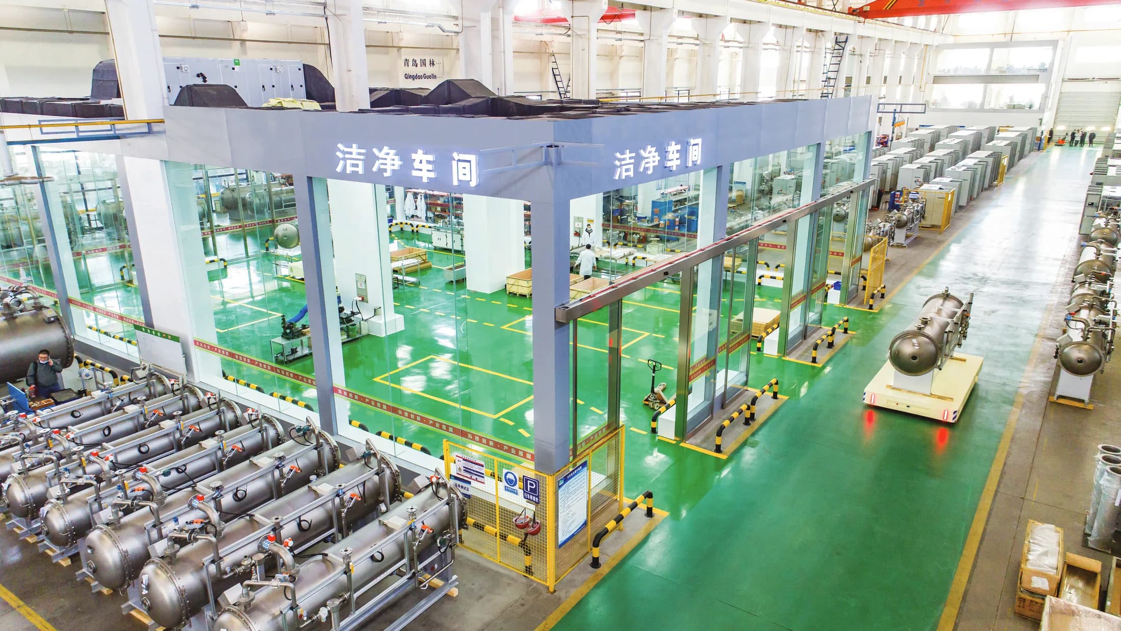
See which equipment, controls, utilities and project interfaces may be included in a complete industrial ozone system—and what every proposal must define.
Buying Guide
Industrial Ozone System Utility Requirements: A Site-Preparation Checklist
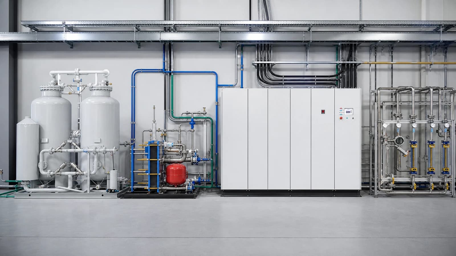
Prepare power, feed gas, cooling, ventilation, drainage, layout and control interfaces for an industrial ozone system using a responsibility-based site checklist.
Buying Guide
How to Prepare an Industrial Ozone System RFQ: A Specification Checklist
Build a comparable industrial ozone system RFQ with a clear design basis, scope boundary, operating cases, bidder response schedule and acceptance requirements.